坐标系的控制是通过 QPainter 类。连同 QPaintDevice and QPaintEngine 类, QPainter 形成了 Qt 的描绘系统的基础。 QPainter 用于履行绘制操作, QPaintDevice 是 2 维空间的抽象,在其中描绘可以使用 QPainter ,和 QPaintEngine 提供用于在不同类型设备中绘制的描绘器接口。
The QPaintDevice 类是可以描绘对象的基类:它的绘制能力被继承由 QWidget , QImage , QPixmap , QPicture ,和 QOpenGLPaintDevice 类。描绘设备的默认坐标系,其拥有位于左上角的原点。 x 值向右递增,和 y 值向下递增。默认单位在基于像素的设备中是 1 像素,而在打印机中是一点 (1/72 英寸)。
映射逻辑 QPainter 坐标到物理 QPaintDevice 坐标的处理是通过 QPainter 的变换矩阵、视口及窗口。默认情况下,逻辑坐标系和物理坐标系重合。 QPainter 还支持坐标变换 (如:旋转和比例缩放)。
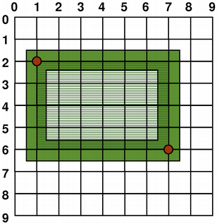
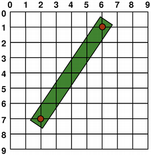
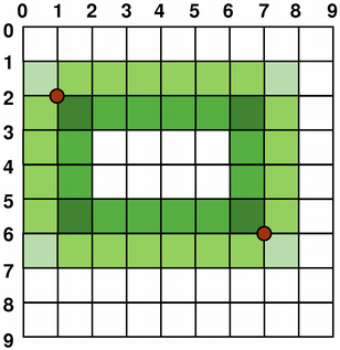
图形图元的大小 (宽度和高度) 始终对应其数学模型,忽略钢笔宽度渲染它采用:
|
|
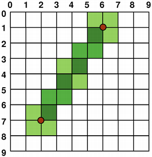
| QRect (1, 2, 6, 4) | QLine (2, 7, 6, 1) |
当绘制时,像素渲染的控制是通过 QPainter::Antialiasing 渲染提示。
The RenderHint 枚举用于将标志指定给 QPainter 可能 (或不可能) 被任何给定引擎遵守。 QPainter::Antialiasing 值指示引擎应对图元边缘抗锯齿若可能的话 (即:通过使用不同颜色光亮度平滑边缘)。
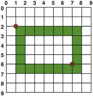
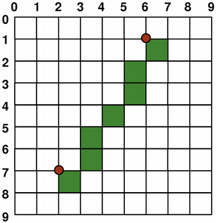
但默认情况下,描绘器 aliased 并应用其它规则:当按 1 像素宽钢笔渲染时,像素将被渲染到 数学定义点的右侧和下方 。例如:
|
|
QPainter painter(this); painter.setPen(Qt::darkGreen); painter.drawRect(1, 2, 6, 4); |
QPainter painter(this); painter.setPen(Qt::darkGreen); painter.drawLine(2, 7, 6, 1); |
When rendering with a pen with an even number of pixels, the pixels will be rendered symetrically around the mathematical defined points, while rendering with a pen with an odd number of pixels, the spare pixel will be rendered to the right and below the mathematical point as in the one pixel case. See the QRectF 以下简图了解具体范例。
| QRectF | ||
|---|---|---|
|
|
|
| 逻辑表示 | 1 像素宽钢笔 | |
|
|
|
| 2 像素宽钢笔 | 3 像素宽钢笔 | |
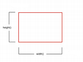
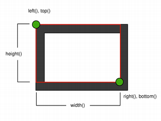
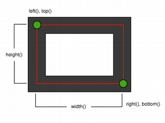
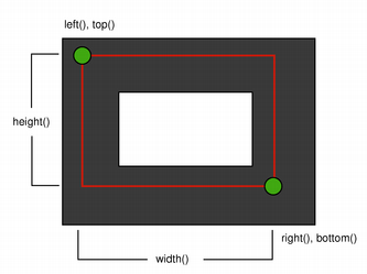
注意,由于历史原因,返回值对于 QRect::right () 和 QRect::bottom () 函数会偏离矩形的真正右下角。
QRect 's right() 函数返回 left() + width() - 1 and the bottom() 函数返回 top() + height() - 1. The bottom-right green point in the diagrams shows the return coordinates of these functions.
推荐只需使用 QRectF 代替: QRectF 类使用浮点坐标定义平面矩形以提高精度 ( QRect 使用整数坐标),和 QRectF::right () 和 QRectF::bottom () 函数 do 返回真正右下角。
另外,使用 QRect ,应用 x() + width() and y() + height() to find the bottom-right corner, and avoid the right() and bottom() 函数。
若设置 QPainter 's 抗锯齿 render hint, the pixels will be rendered symetrically on both sides of the mathematically defined points:
|
|
QPainter painter(this); painter.setRenderHint( QPainter::Antialiasing); painter.setPen(Qt::darkGreen); painter.drawRect(1, 2, 6, 4); |
QPainter painter(this); painter.setRenderHint( QPainter::Antialiasing); painter.setPen(Qt::darkGreen); painter.drawLine(2, 7, 6, 1); |
默认情况下, QPainter 运转于关联设备自己的坐标系统中,但它还拥有对仿射坐标变换的完整支持。
You can scale the coordinate system by a given offset using the QPainter::scale () function, you can rotate it clockwise using the QPainter::rotate () function and you can translate it (i.e. adding a given offset to the points) using the QPainter::translate () 函数。
|
|
|
|
| nop | rotate() | scale() | translate() |
You can also twist the coordinate system around the origin using the QPainter::shear () function. All the transformation operations operate on QPainter 's transformation matrix that you can retrieve using the QPainter::worldTransform () function. A matrix transforms a point in the plane to another point.
If you need the same transformations over and over, you can also use QTransform objects and the QPainter::worldTransform () 和 QPainter::setWorldTransform () functions. You can at any time save the QPainter 's transformation matrix by calling the QPainter::save () function which saves the matrix on an internal stack. The QPainter::restore () function pops it back.
One frequent need for the transformation matrix is when reusing the same drawing code on a variety of paint devices. Without transformations, the results are tightly bound to the resolution of the paint device. Printers have high resolution, e.g. 600 dots per inch, whereas screens often have between 72 and 100 dots per inch.
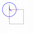
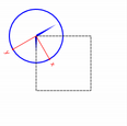
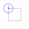
| 指针式时钟范例 | |
|---|---|
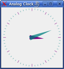
|
The Analog Clock example shows how to draw the contents of a custom widget using
QPainter
's transformation matrix.
We recommend compiling and running this example before you read any further. In particular, try resizing the window to different sizes. |
void AnalogClockWindow::render(QPainter *p)
{
    static const QPoint hourHand[3] = {
        QPoint(7, 8),
        QPoint(-7, 8),
        QPoint(0, -40)
    };
    static const QPoint minuteHand[3] = {
        QPoint(7, 8),
        QPoint(-7, 8),
        QPoint(0, -70)
    };
    QColor hourColor(127, 0, 127);
    QColor minuteColor(0, 127, 127, 191);
    p->setRenderHint(QPainter::Antialiasing);
    p->translate(width() / 2, height() / 2);
    int side = qMin(width(), height());
    p->scale(side / 200.0, side / 200.0);
We translate the coordinate system so that point (0, 0) is in the widget's center, instead of being at the top-left corner. We also scale the system by
This will give us a 200 x 200 square area, with the origin (0, 0) in the center, that we can draw on. What we draw will show up in the largest possible square that will fit in the widget. 另请参阅 窗口/视口转换 章节。
    QTime time = QTime::currentTime();
    p->save();
    p->rotate(30.0 * ((time.hour() + time.minute() / 60.0)));
    p->drawConvexPolygon(hourHand, 3);
    p->restore();
We draw the clock's hour hand by rotating the coordinate system and calling QPainter::drawConvexPolygon (). Thank's to the rotation, it's drawn pointed in the right direction.
The polygon is specified as an array of alternating
x
,
y
values, stored in the
调用 QPainter::save () 和 QPainter::restore () surrounding the code guarantees that the code that follows won't be disturbed by the transformations we've used.
    p->save();
    p->rotate(6.0 * (time.minute() + time.second() / 60.0));
    p->drawConvexPolygon(minuteHand, 3);
    p->restore();
We do the same for the clock's minute hand, which is defined by the four points (1, 0), (0, 1), (-1, 0), and (0, -40). These coordinates specify a hand that is thinner and longer than the minute hand.
    p->setPen(minuteColor);
    for (int j = 0; j < 60; ++j) {
        if ((j % 5) != 0)
            p->drawLine(92, 0, 96, 0);
        p->rotate(6.0);
    }
Finally, we draw the clock face, which consists of twelve short lines at 30-degree intervals. At the end of that, the painter is rotated in a way which isn't very useful, but we're done with painting so that doesn't matter. |
|
For more information about the transformation matrix, see the QTransform 文档编制。
当描绘采用 QPainter ,使用逻辑坐标指定点,然后转换成描绘设备的物理坐标。
逻辑坐标到物理坐标的映射的处理是通过 QPainter 的世界变换 worldTransform() (described in the 变换 章节),和 QPainter 's viewport() and window() . The viewport represents the physical coordinates specifying an arbitrary rectangle. The "window" describes the same rectangle in logical coordinates. By default the logical and physical coordinate systems coincide, and are equivalent to the paint device's rectangle.
Using window-viewport conversion you can make the logical coordinate system fit your preferences. The mechanism can also be used to make the drawing code independent of the paint device. You can, for example, make the logical coordinates extend from (-50, -50) to (50, 50) with (0, 0) in the center by calling the QPainter::setWindow () 函数:
QPainter painter(this);
painter.setWindow(QRect(-50, -50, 100, 100));
Now, the logical coordinates (-50,-50) correspond to the paint device's physical coordinates (0, 0). Independent of the paint device, your painting code will always operate on the specified logical coordinates.
By setting the "window" or viewport rectangle, you perform a linear transformation of the coordinates. Note that each corner of the "window" maps to the corresponding corner of the viewport, and vice versa. For that reason it normally is a good idea to let the viewport and "window" maintain the same aspect ratio to prevent deformation:
int side = qMin(width(), height())
int x = (width() - side / 2);
int y = (height() - side / 2);
painter.setViewport(x, y, side, side);
If we make the logical coordinate system a square, we should also make the viewport a square using the QPainter::setViewport () function. In the example above we make it equivalent to the largest square that fit into the paint device's rectangle. By taking the paint device's size into consideration when setting the window or viewport, it is possible to keep the drawing code independent of the paint device.
Note that the window-viewport conversion is only a linear transformation, i.e. it does not perform clipping. This means that if you paint outside the currently set "window", your painting is still transformed to the viewport using the same linear algebraic approach.
The viewport, "window" and transformation matrix determine how logical QPainter coordinates map to the paint device's physical coordinates. By default the world transformation matrix is the identity matrix, and the "window" and viewport settings are equivalent to the paint device's settings, i.e. the world, "window" and device coordinate systems are equivalent, but as we have seen, the systems can be manipulated using transformation operations and window-viewport conversion. The illustration above describes the process.
另请参阅 指针式时钟窗口范例 .